Gunnplexer
Application Notes
Two-Way Communications
It is anticipated that the primary application
of the Gunnplexer "front end" will be for two-way communications
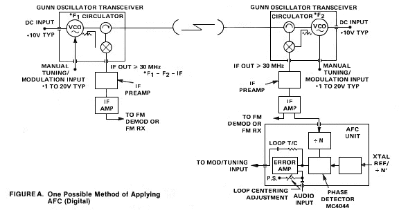
(Figure A). For this application, two units, are used with their
carrier frequencies offset to provide a reasonable i-f (30, 40,
144 MHz or higher). At any given time, one unit is used as a transmitter,
and the other a receive down converter. It should be noted that
the frequency stability of the unit is such that in most cases
some sort of afc is desirable. The purpose is to provide a corrective
tuning voltage to keep the i-f at a constant frequency. The units
lend themselves well to relaying remote receivers to repeater
sites at VHF, etc. all of which places a premium on reliable 24
hour communications. At the other end of the scale these units
may also be used by the amateur microwave DX enthusiast chasing
records at straight line of sight, refractive and "ducting"
paths. Here the user should use a low noise i-f preamplifier,
as narrow band receivers as possible, and high gain dish antennas.
With omni directional antennas the units may also be used as microwave
beacons.

A separate power supply and modulator must be provided.
It is suggested that the transceiver be used in conjunction with
the MA86551 (17 dB) horn antenna. The half power beamwidth in
both planes is 30 degrees. Alternate antennas are available.
Practical Range Considerations
The actual usable range of the M/A-Com
transceiver "front end" is a function of the transceiver
characteristics such as output power, frequency stability and
noise figure; ERP as affected by the antenna gains at both ends,
and equally important, the characteristics of the associated i-f
receiver (in particular its signal-to-noise ratio and bandwidth).
In general, it is desirable to deviate the FM signal such that
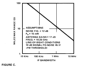
the available i-f bandwidth is completely filled. The graph in
Figure C indicates the maximum achievable range vs. i-f bandwidth
assuming a 17 dB gain horn at both ends. The range shown is at
"threshold" (defined as the beginning of intelligible
speech). The range indicated allows no fade margin. Severe fades
will not only affect the "threshold" as defined above
but could also cause the system afc to unlock. Conservative practice
would indicate shorter ranges than indicated, depending on the
environment, including rainfall, multipath effects, etc. Obviously,
providing higher gain antennas will increase range but at the
expense of increased costs both for the dishes and their stable
mounts.
Mixer/IF Interface
In order to achieve optimum noise figure
and prevent undesired pick up, the i-f amplifier connection to
the i-f output on the mixer should be shielded and be kept as
short as possible. The unit is supplied with a 1,000 ohm load
resistor to prevent damage to the receiver diode. The 1,000 ohm
resistor provides a dc return for the mixer diode. In actual experience,
a noise figure as low as 10 dB is achievable if some care is taken.
In most cases the resistor should be removed since it can degrade
noise figure. Actual measured impedance at 30 MHz is approximately
200 ohms. The impedance can vary from transceiver to transceiver;
however, an improvement in receiver sensitivity will result if
some effort is made to match the diode/i-f interface. The noise
figure of the i-f preamplifier will obviously affect the performance
of the receiver and for those who need maximum sensitivity, it
is suggested that a separate i-f preamplifier be constructed using
a suitable low noise transistor or FET. When operating with a
standard 88-108 FM receiver, make sure that the antenna input
is unbalanced.
Achieving Oscillator Frequency
Stability
Keeping an oscillator with a maximum
drift of -350 KHz per degree centigrade centered in an i-f bandwidth
of, say, 200 kHz obviously requires some engineering ingenuity.
The daily change in outside temperature can be as large as 25°
C (8.l75 MHz maximum) per day, but over periods of one hour, 10°
C (3.5 MHz maximum) change would be unusual. In almost all cases,
once the transceiver has reached thermal equilibrium with its
environment, the changes are relatively graceful. The electronic
tuning range, 60 MHz, allows adequate capacity to accommodate
for the frequency shifts even when modulated with video. The frequency
drift over a short period of time can usually be corrected by
adjusting the varactor bias manually. For reliable, long term
use such as receiver remotes for a VHF/UHF repeater, the user
may wish to consider more sophisticated approaches. The first
is to reduce the amount of the drift by placing the transceiver
in a temperature-controlled environment such as produced by a
crude oven using a thermostatic-controlled heater or light bulb.
The advanced experimenter may even wish to use proportional control.
The second approach involves electronic automatic frequency control
of which many variations are possible ranging from the most sophisticated,
using combinations of a digital afc/phase lock shown in Figure
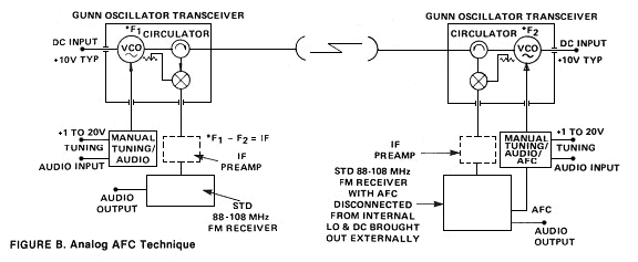
A, to the simple commercial FM receiver with afc shown in Figure
B. In both cases, one VCO is allowed to "float", and
the frequency of the second is adjusted electronically to the
first in such a manner to provide a constant intermediate frequency
to the i-f receiver.

In the first more sophisticated approach shown in
Figure A, the i-f is divided by n and a stable crystal oscillator,
by n' and the phases of the two outputs compared at a frequency
in a phase detector. The dc output of the detector is fed through
an error amplifier to the varactor on the VCO. The audio input
and loop centering controls are also shown. The shunting RC network
allows the modulation frequencies to bypass the error amplifier.
In the event that the unit breaks "lock", some users
may wish to design a "search" mode into the afc loop.
The second, using the traditional analog approach, is shown in
Figure B and utilizes a 88-108 MHz standard FM broadcast receiver
of good quality as the i-f receiver. This receiver must be modified
to disable the afc control on the internal LO, and to transfer
afc control to the Gunn oscillator. This afc voltage, when combined
with the manual tuning control and the audio modulation, is applied
to the tuning varactor of the VCO. The second transceiver also
uses an FM receiver for an i-f receiver. However, in this case,
no modification is necessary since the second VCO is not afc controlled
but it must be tuned initially to the same frequency as the first
FM receiver. This system allows the user to correct manually either
with the manual tuning control of the varactor power supply or
by the frequency control of the FM receiver. The user is cautioned
to place the VCO with the afc control on the correct frequency
side of the other VCO so that the frequency corrections converge
rather than diverge. In actual practice, some on-the-air "tweaking"
of the manual controls will be necessary to ensure that the units
center in the i-f passband and the afc "locks up".

Radar
A single transceiver can be used as an
FM doppler radar. When the varactor diode is modulated, the reflected
received signal provides an audio/video i-f signal which has a
frequency proportional to the velocity of the object moving toward
or away from the transceiver, plus the round trip time frequency
deviation. The round trip time frequency deviation contains the
target range information. Intended applications include distance
measurement, speed measurement, direction monitoring and intrusion
alarms. For further information on the application, write for
the M/A-Com brochure entitled "Microwave Components for Motion
Detection".